The Apollo and latterly Garmin SL-30 was and indeed is a great bit of kit, providing Nav and Com functions in a pleasingly small package. But for those who fly in Europe, its lacking one important thing – 8.33 capability on the Com side.
Many owners have continued to use their existing SL-30s as a back-up radio, suitably placarded to show non-compliance with 8.33 requirements. And the reason why is usually not hard to fathom. The small size of the Sl-30, so much a blessing when originally installed turns out to be a curse when it comes to replacement. All the available 8.33 complaint boxes are bigger. And if you have. tight stack, that’s a problem!
We were asked to look swapping an Sl-30 in and RV-10 for a Garmin GNC-255. The new Garmin is just four-tenths of an inch taller than the SL-30 but when there is little or no space, that’s a big problem.
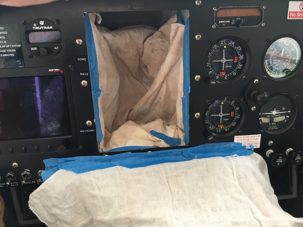
Close inspection of the existing stack indicated that there might be perhaps two-tenths of an inch to be had by moving everything down. At the top, there was space for a two-tenths cut-out in the panel, but what about clearance on the back of the avionics under the glare shield? Trickier… The only way to find out was to pull the existing kit out. With some careful rearrangement and cutting away of a small non-structural support behind the instrument panel it appeared to be just be possible to ease the audio panel into the top slot in the stack.
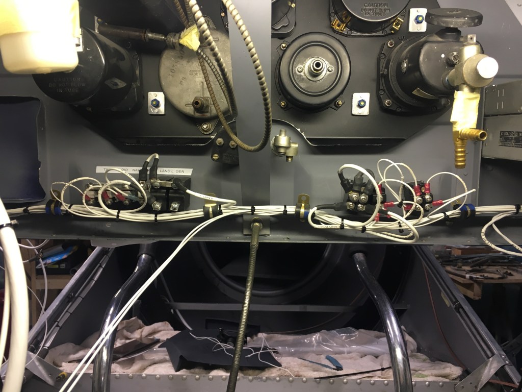
The original wiring was to say the last ‘tight’. Without service loops, it was impossible to draw the connectors out of the panel and the prospect of re-pinning them in situ was not not an attractive one.
The owner had also asked if it was possible to couple the GNS 530 to an existing autopilot. Time taken thinking is time saved grafting so the fist task is to work out what needs to connect to what. The Garmin GNS530 has some interesting undocumented features regarding the ability to (not) output Aviation Format data on more than one port. This requires a ‘fix’ in the form of spliced connections. Time for a diagram.
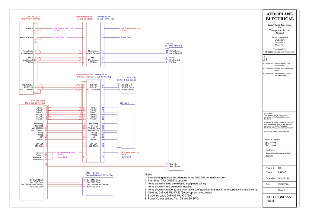
The owner had also asked if it was possible to couple the GNS 530 to an existing autopilot. Time taken thinking is time saved grafting so the fist task is to work out what needs to connect to what. The Garmin GNS530 has some interesting undocumented features regarding the ability to (not) output Aviation Format data on more than one port. This requires a ‘fix’ in the form of spliced connections
Taking great care to mask-up and protect the existing panel, it was then out with the metalwork tools and set to work to enlarge the panel aperture. remove and refit the instrument support rails and make new rear supports. Unlike to previous installer, we opted to fit captive nuts all around. The time taken in fitting these is saved many times over in the installation process alone and the ease of future maintenance assured.
Given the difficulty in working on the installed wiring, we elected to make a patch-harness to going the old SL-30 wiring to the new GNC255, with the addition of a couple of extra cables to facilitate a direct feed of Nav data to the installed autopilot. If nothing else it can all be tested on the bench prior to installation

Given the tightness of the installation it proved quite tricky to assemble the various boxes in the panel and connect all the connectors. You have got to hope it all works correctly when you switch it on as the prospect of taking it all apart again to correct one bad wire is not a very attractive one.
Sure enough, it all worked first time….